


 +44 (0)1455 848 411


What are carriers?
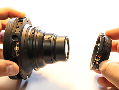
In the context of rehousing lenses, you’ll often hear the terms ‘carrier’ or ‘carriers’, so what are they exactly? This term is referring to the mechanical part of the lens that carries the optical unit(s) fore/aft inside the chassis of the lens. Carrier(s) are often described when referring to a cam-based focus system. If a cam is being used to move a follower fore/aft, it is driving something internally that is holding the optical unit(s) within the mechanism. On a higher end rehousing, the optical unit(s) will be separated from the original mechanics. Once ready to install into the new metalwork, the cylindrical tube that holds the glass will be fixed to the carrier. In some cases, the glass elements will be loaded individually into the new carrier, depending on the design and how much space there is internally for the new mechanics. If a new iris assembly is being installed into the rehoused lens, this will also be built into the carrier in the correct position.
Image: Installing rear carrier
There are two main ways for a carrier to travel within the chassis of a lens. One method is to use running surfaces. This requires a tight tolerance on machining the components to ensure a smooth movement while offering no play. If there is any play between the running surfaces, this will result in image shift when pulling focus. Due to the inherent complications with accurately anodising aluminium, running surfaces are often machined slightly oversized. Once the part has been anodised, it will then have the final machining pass done on the running surfaces to produce the best finish possible. Another option would be to use brass in this scenario, however brass is not easy to blacken and is considerably heavier than aluminium. The running surfaces on the carrier would now be a perfect fit inside the bore of the chassis to allow the optical unit(s) to slide fore/aft to control the focus movement. This method has some drawbacks though. Quite often, this will leave two running surfaces touching each other that are bare aluminium. Therefore, grease is used to aid the movement and to prevent the two parts from binding against each other. This requires regular servicing to keep the lens in optimal working condition. As the lens is used, contamination will work its way into these areas. As the running surfaces slide against each other, they will grind down any tiny particles and become trapped in the grease. This leads to the grease becoming a carrier of tiny particles, which over time will act like a grinding paste and wear away material from the running surfaces. Not only would you start to feel this (the focus movement would become less smooth), but you would also notice image shift when pulling focus. Once the wear of the lens reaches this point, the only remedy is to begin replacing parts.

Image: This image displays one of our roller assemblies installed in to what we call the pocket of the carrier, depending on the carrier size and or style will determine how many pockets and therefore bearings each carrier has. As a rule of thumb most of our carriers have 4 bearings each but the majority of our lenses have a front and a rear carrier, which then totals to 8 bearings altogether.
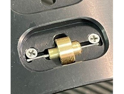
Another option is to use bearings instead of running surfaces. To prevent impossibly tight tolerances on the machining, it is necessary to have these bearing sprung loaded to keep constant pressure and prevent any image shift in the lens system. The bearings can either be mounted on the chassis of the lens or installed into the carrier. Initially, it makes mechanical sense to have the miniature bearings installed into the chassis, therefore the carrier holding the optical unit(s) will smoothly move fore/aft within the chassis. However, the carrier holding the optical unit is nearly always cylindrical shape in its design. Due to the flat face of the miniature bearing, it means that the contact point of the outer race to the chassis is very small. Ultimately, it is just running on one point per bearing used. There are two main disadvantages with this method. Due to the tension of the sprung loaded carrier, it creates wear on the small contact points (though much slower than in the running surfaces example), but it also creates a high stress point on the bearing. This can cause the outer race of the miniature bearing to crack if the lens has any impact damage.
Image: A brass roller assembled with the bearing inside the boot, on a spindle. The wire is used to control the tension for the roller bearings within the chassis.
If we were to swap this design around and have the bearings on the carrier, you increase the amount of surface area in contact with the bearing. However, the contact point is now on the two outer edges of the bearing. Again, this is going to cause wear over time as well as the high stress point mentioned above. To overcome this, TLS manufacture a brass ‘boot’ that pushes onto the outer race of the miniature bearing. This brass boot replicates the outer race of the bearing, however this time the edge has a radius on it to match the exact bore diameter of the chassis. This creates a relatively large contact surface area as well as providing additional strength to the outer race of the bearing. This significantly increases the longevity of the lens, increases the impact resistance and increases the amount of time needed between service intervals.
Whichever method is used to create the carrier(s) and their movements, it is critical to get the alignment correct within the main housing. Not only do the optical unit(s) need to be concentric, but they also need to be square in relation to the film plane and to each other. This needs to be true throughout the movement from infinity to close focus too. Any misalignment will result in discrepancies with the image produced by the lens.
If you would like to discuss this topic further or have any questions about the rehousing process, please get in touch with us at sales@truelens.co.uk or calling our office on +44 (0)1455 848411.